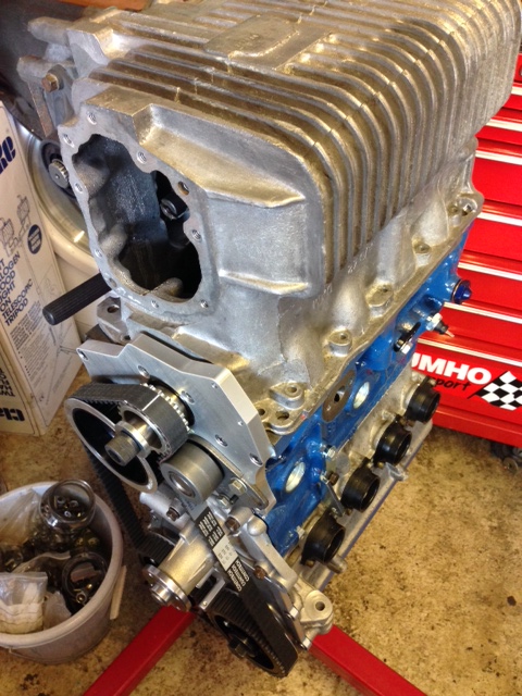
Once the jackshaft was in and the pulleys fitted the engine was assembled in modular format. The cylinder head was re-assembled and checked again once the camshaft was returned from Piper. The re-profiling worked and the valve gap issue was resolved. This could then be fitted. I used SC’s Silicone / copper head gasket for ease of assembly. Head studs of the 8V K100 engine arrangement have to be shortened in all positions (by approx 7mm in my application). The original BMW head bolt washers are used with new A series flanged head nuts. SC specifies all torque values and tightening sequence in the build manual. Once complete spacing between each camshaft and fasteners have to be checked. A new cast large impeller (without bypass output) water pump was fitted. This needs to be modified along the top edge of the alternator top mount point. This modification is removing material so it allows the cylinder head / SC end cover plate to sit above the water pump body. The original mounting hole is used so care is needed to be taken when modifying to remove enough material to allow the water pump to fit but minimum material to prevent weakening of the alternator mounting. Also a cast rib on the front edge of the water pump needs to be ground back to allow sufficient clearance for the timing belt to run past from crankshaft pulley to inlet cam gear.
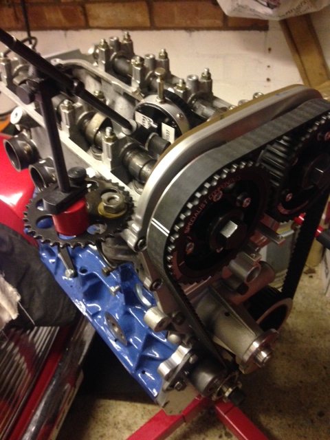
Basic cam timing of the engine could then take place. This was completed over the course of an afternoon and checked, double checked and triple checked with various belt / pulley adjustments involved. After adjustments the cam timing was set to SC’s instructions. An accurate DTI is an important and essential tool in this job and also mounting it so it acts in parallel with the inlet valve . The engine was then rotated carefully by hand to see if there was any issues with interferance but everything was fine. Tension of the belt is measured on the length of belt from the exhaust cam to the oil pump (jackshaft) pulley. This is rotation level between thumb and index finger. Its adjusted by the cam tensioner roller as shown at the bottom of the picture. From past projects when this turned up in the SC kit it is from a Ford Pinto engine. This is the cam belt tensioner type if parts are required. The ford part number is: 1 496 915. I will get the details of the belt from the continental model number.
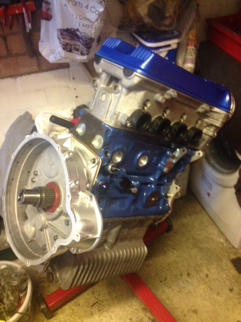
The gearbox was then fitted to the engine body, followed by the MED Roller bearing drop gears, transfer casing and MED clutch and flywheel assembly. Below is the result…


Hi there ihave just cum across your blog. In the photo of he cam side of the engine where you are fitting the bottom pulleys, did you have to space it out by 4mm so it did not rub on the jack oil pulled as i,m having this problem
Hi Jason, are you saying you are having clearance issues with the crankshaft pulley touching the oil pump jackshaft pulley? If so have you removed the spot welded tin ring from the stardard crank pulley? I did not have to space any of my setup that I can remember.
It,s a mpi engine so the bottom dampener is a ply vee belt. The photos of your looked as you had that same set up
Hi Jason. Oh ok. I think you have viewed a picture of a Specialist components display engine that I took a few pictures of when I purchased my kit from them. Is this the orange block engine. This engine runs a later MPI crank pulley to run a supercharger belt. I’m using an original V belt 1275A+ pulley so i’m not that familiar with the mounting of the MPI pulley. John or Simon at SC will be able to give you a quick answer if you drop them a call or email on this one. Sorry I couldn’t be of more help.
I have spoke to them and that what they said. But when i saw the photo on your blog it just confused me. Thanku for your reply.