Posts Tagged ‘ARP’

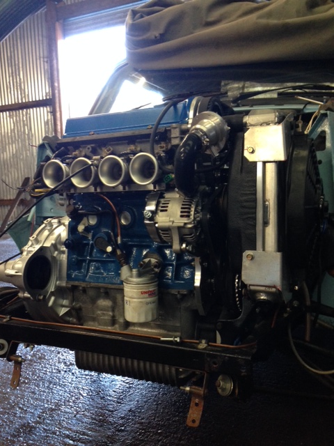
So the final push to connect all the oil and water unions / hoses and hose clips was on and to try and get the engine running. I had to purchase a pre engaged starter and wire that in removing the inertia remote solenoid and related wiring from the old car setup. Once oil and water had been filled and the complete system checked for leaks i attempted a crank to check oil pressure. Gulp….. Nothing. After running through the basics, oil level again, box to engine block bolts and finding nothing i attempted back filling the oil pressure switch drilling and rotating the engine backwards to draw oil into the oil pump. The oil was drawn in and again i tried a short crank to check oil pressure. Still nothing. At this point I went home to think.

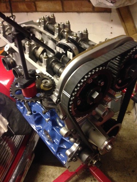
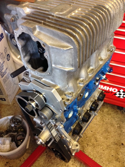
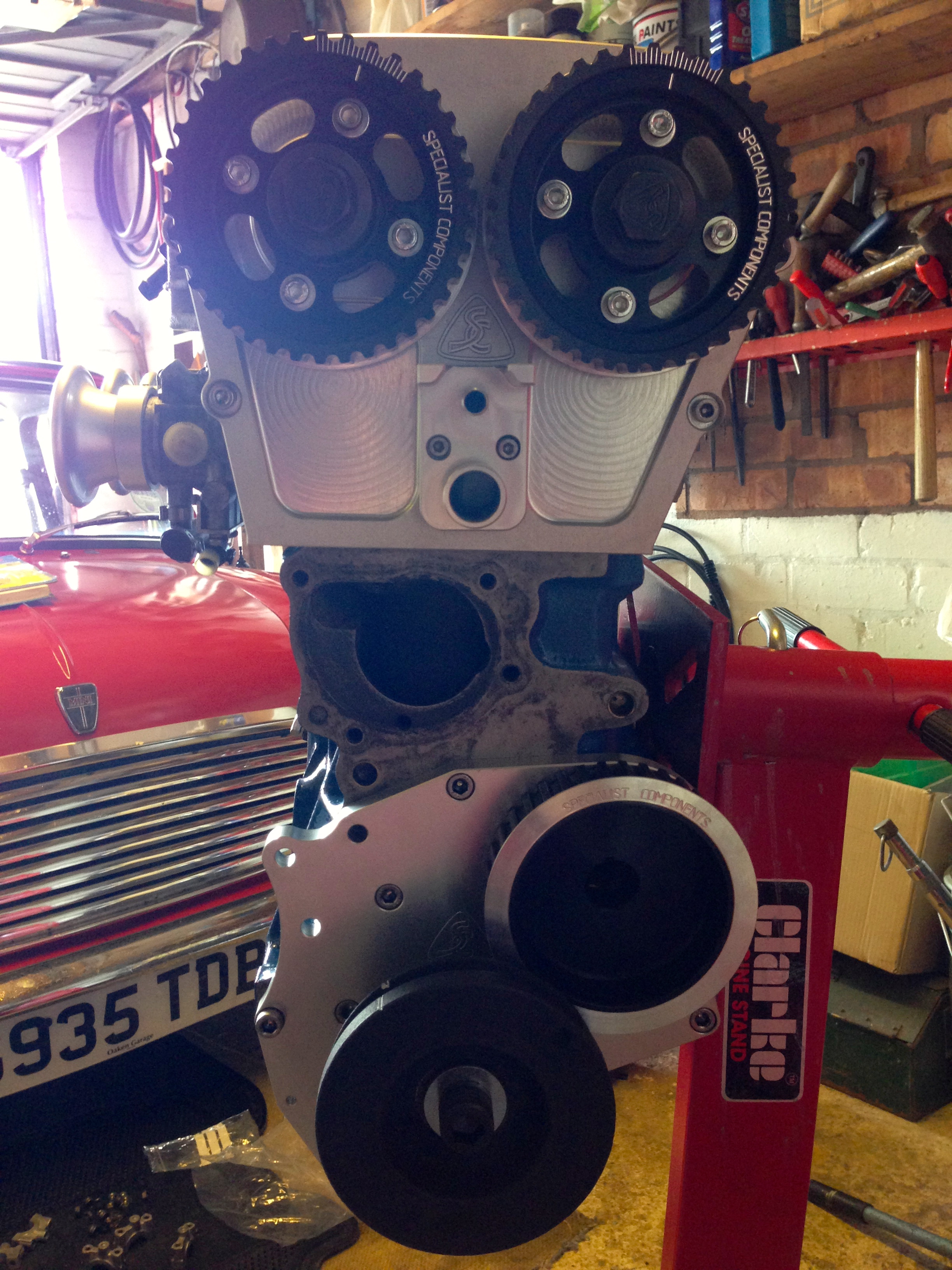
After going through all possibilities of the o-ring missing situation, the oil pump gasket rotating when fitting leaving the bung in the central oil pickup pipe i was getting frustrated of having to think the engine would have to come out to check it all again. The next evening i went back to the car and timed up the engine to remove the timing belt i was thinking perhaps the oil pump wasn’t rotating fast enough to draw oil up from the sump. As the old camshaft is now an oil pump jackshaft i connected a battery drill to a socket and spun up the oil pump. Bingo finally a healthy oil pressure showing on the gauge. After refitting and checking the timing again by hand turning i connected up the laptop and opened up SXTune. I wanted to check if the ECU was picking up a signal and showing an RPM from the engine it was after a couple of adjustments getting the crank sensor aligned. I then checked if we had spark at the plugs. Again yes.

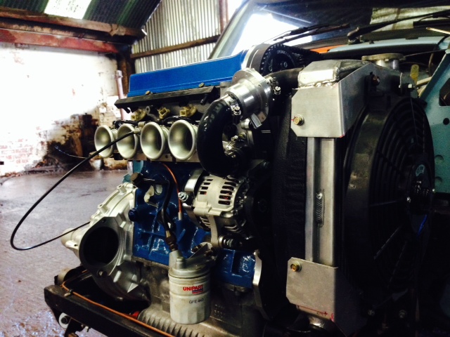
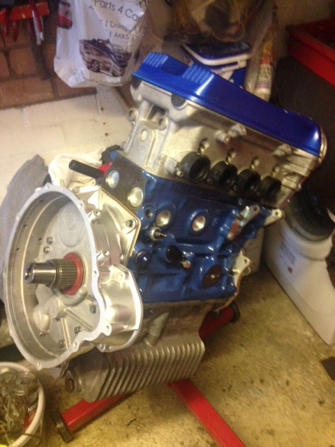
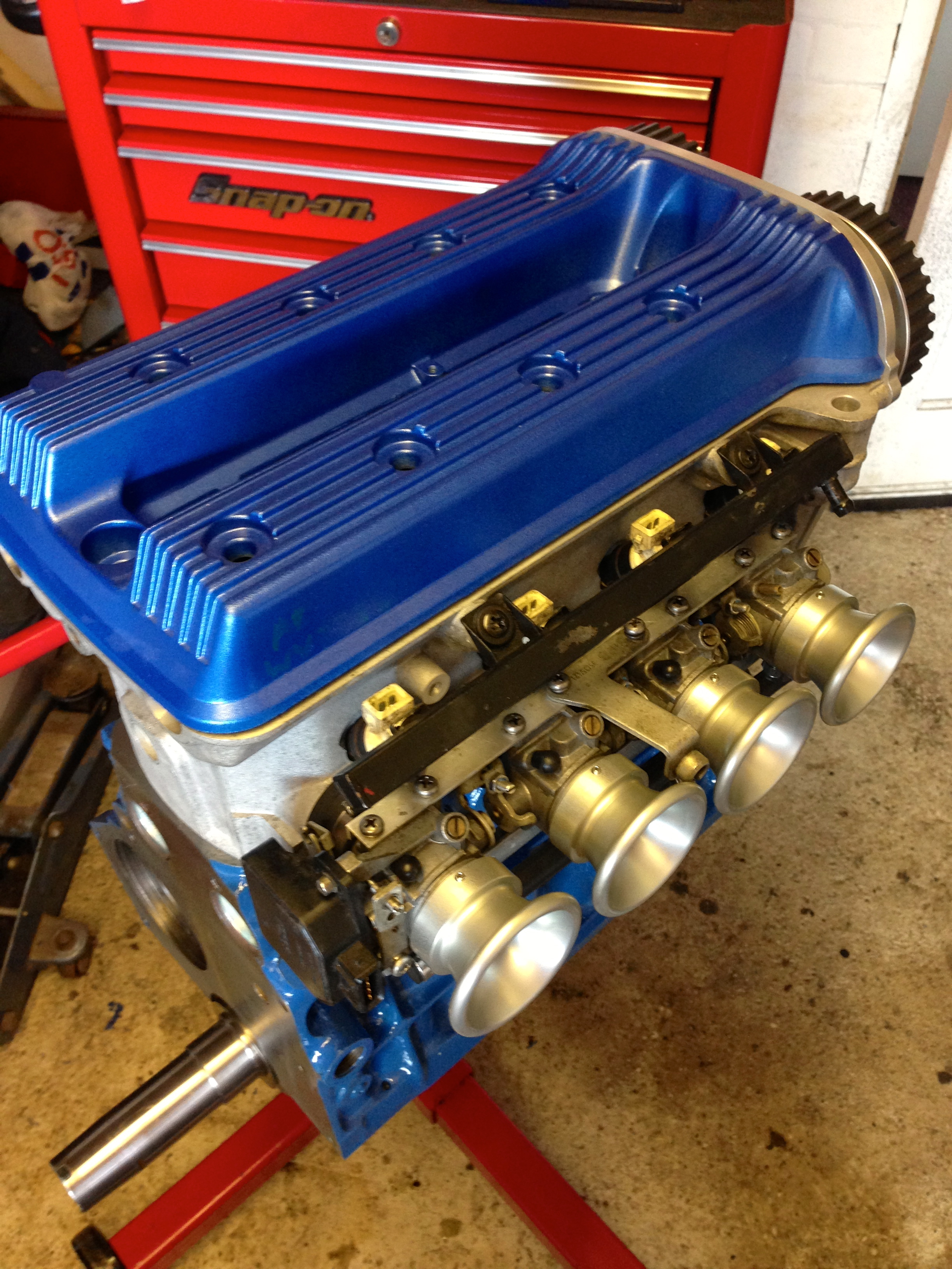
That weekend i completed the fuel lines, filter, fuel pump and final bits and bobs in the engine bay and stuck a couple of gallons of fresh unleaded in the tank. On the second or third crank it kicked up. After a minute of the occasional cough messing with the throttle bodies it ran. It ran perfectly at about 900-1000RPM. Noticeably it was so quiet at the front end. No rattling of pushrods followers or timing chains now. Even though it ran nice it wouldn’t rev and it really needs to go on a rolling road to be properly set up I think i managed maybe 1200RPM maximum by just touching the throttle linkage.

Finally i have to complete the wiring for the alternator circuit and the relays need to be plumbed in properly to operate the fuel pump and the cooling fan.

photo 1-7

photo 2-7

photo 4-4

Advertisement

Once the jackshaft was in and the pulleys fitted the engine was assembled in modular format. The cylinder head was re-assembled and checked again once the camshaft was returned from Piper. The re-profiling worked and the valve gap issue was resolved. This could then be fitted. I used SC’s Silicone / copper head gasket for ease of assembly. Head studs of the 8V K100 engine arrangement have to be shortened in all positions (by approx 7mm in my application). The original BMW head bolt washers are used with new A series flanged head nuts. SC specifies all torque values and tightening sequence in the build manual. Once complete spacing between each camshaft and fasteners have to be checked. A new cast large impeller (without bypass output) water pump was fitted. This needs to be modified along the top edge of the alternator top mount point. This modification is removing material so it allows the cylinder head / SC end cover plate to sit above the water pump body. The original mounting hole is used so care is needed to be taken when modifying to remove enough material to allow the water pump to fit but minimum material to prevent weakening of the alternator mounting. Also a cast rib on the front edge of the water pump needs to be ground back to allow sufficient clearance for the timing belt to run past from crankshaft pulley to inlet cam gear.

Basic cam timing of the engine could then take place. This was completed over the course of an afternoon and checked, double checked and triple checked with various belt / pulley adjustments involved. After adjustments the cam timing was set to SC’s instructions. An accurate DTI is an important and essential tool in this job and also mounting it so it acts in parallel with the inlet valve . The engine was then rotated carefully by hand to see if there was any issues with interferance but everything was fine. Tension of the belt is measured on the length of belt from the exhaust cam to the oil pump (jackshaft) pulley. This is rotation level between thumb and index finger. Its adjusted by the cam tensioner roller as shown at the bottom of the picture. From past projects when this turned up in the SC kit it is from a Ford Pinto engine. This is the cam belt tensioner type if parts are required. The ford part number is: 1 496 915. I will get the details of the belt from the continental model number.

camtiming

The gearbox was then fitted to the engine body, followed by the MED Roller bearing drop gears, transfer casing and MED clutch and flywheel assembly. Below is the result…

Gearbox fitting


Engine assembled

photo 3-3

So again due to lack of time at present the engine project has been on the back burner for another month. But on friday i opened up the parts that had been returned from Chris and got the build underway. I picked up new big end, mains and thrust bearings from Mini spares centre Midlands on Friday afternoon and got the crank and mains in and torqued down on friday night.

This morning i started early’ish and managed to get the rods and pistons in. Time was taken with this and it all went smoothly should i say myself.

I have mocked up the basic engine to get some more pictures to show viewers following this. I tried to pick up a water pump today but couldn’t find anywhere local with one in stock. Ill grab one of these next week now from Mini spares and then carry out the modifications to the top edge and alloy web removal.

I did come across a couple of niggles, i still need to modify the original camshaft to allow oil flow to the cams. I spoke to John at SC in the week regarding this and he was helpful and sent me over a picture showing how SC tackle the modification. Ill add a picture of this on maybe the next post. Also one of the bottom plate mounting holes to the man journal cap drilling is slightly off with my block so this will need a modification to address the issue. The head studs all have to be cut down in the 8v head configuration so an estimated 10mm will need to be taken off these for clearance purposes.

So theres plenty of work left to get through but the projects coming together nicely now…. finally.

Click on thumbnails for full size pics.

Cheers

Ad

Crank_1

IMG_1611

IMG_1613

IMG_1615

IMG_1617

IMG_1619

IMG_1625

IMG_1627

IMG_1631