So 2015… Its been a long time coming, but finally its time to get back and finish what began back in 2006. A lot has happened since my last post but the mini has not been forgotten or sold and we are still in a good position to get it completed. I may have a little extra maintenance work on rear brakes and a lot of cleaning parts up up as we go etc but this will give me the opportunity to tweek those little parts that bugged me and change the odd part here and there.
Talking bout changing the odd part. I have a new addition that I will be touching on using this blog. Its mini related so don’t go anywhere. What we are talking about is a one owner Old English White mk1 1966 Morris mini minor super deluxe that has been sitting in storage since 2015. Probably since approximately the last time I updated this page. I won’t go into too much detail but over the last 2 or 3 months I have been recommissioning the safety critical items and confirming that yes this can go back on the road. Now that the car is Tax and MOT exempt there is a little paperwork that I need to go through to get it road legal. I will also be taking it to my local MOT station to have it checked over fully just incase I have missed anything. Im taking the opportunity to replace all of the perishable parts within the braking system as well as new tyres and just tiding it up. There was a plan to strip it and send it away to have the shell rebuilt, this may still happen. But for now lets just get it back on the road and maybe put on 500 miles.
So back to the main Twincam mini. So where I left it was, I had some suspension parts to refit and drop the car back to the floor. The engine does run but the tune is off, it idles but its way off on pickup. I have a wide-band o2 sensor from SC to fit into the LCB and this will send a signal to the eco that I can monitor. Ill need to drain the fuel tank and drop some fresh 98OCT super unleaded in, swap the plugs and drop the oil. Once this is complete ill compile a list of jobs to start ticking off and update this and my Instagram @adder501 with my progress.
Thanks for staying tuned
Adam
Looks like summer is on its way. Looking forward to finishing off the engine and getting it rolling road tuned in the near future.
Has anyone got any videos other than the ones on youtube that can be found of k100,k1100,k1200 engined minis on the road???????
POST THE LINKS UP OR SEND A “CONTACT ME” MESSAGE OR IF ANYONE HAS A BLOG OR PAGE SIMILAR TO THIS ONE AND THEY WOULD LIKE ME TO LINK IT ON MY LINKS PAGE CONTACT ME.
Cheers
Adam
Final work prior to starting.
Posted: January 17, 2015 in Block, HeadTags: alloy radiator, ARP, bmw, classic mini, engine, engine conversion, engine running, its alive, k100, lightweight, mini, Mini Twin cam, radtec, stainless manifolds, TWIN CAM.
So the final push to connect all the oil and water unions / hoses and hose clips was on and to try and get the engine running. I had to purchase a pre engaged starter and wire that in removing the inertia remote solenoid and related wiring from the old car setup. Once oil and water had been filled and the complete system checked for leaks i attempted a crank to check oil pressure. Gulp….. Nothing. After running through the basics, oil level again, box to engine block bolts and finding nothing i attempted back filling the oil pressure switch drilling and rotating the engine backwards to draw oil into the oil pump. The oil was drawn in and again i tried a short crank to check oil pressure. Still nothing. At this point I went home to think.
After going through all possibilities of the o-ring missing situation, the oil pump gasket rotating when fitting leaving the bung in the central oil pickup pipe i was getting frustrated of having to think the engine would have to come out to check it all again. The next evening i went back to the car and timed up the engine to remove the timing belt i was thinking perhaps the oil pump wasn’t rotating fast enough to draw oil up from the sump. As the old camshaft is now an oil pump jackshaft i connected a battery drill to a socket and spun up the oil pump. Bingo finally a healthy oil pressure showing on the gauge. After refitting and checking the timing again by hand turning i connected up the laptop and opened up SXTune. I wanted to check if the ECU was picking up a signal and showing an RPM from the engine it was after a couple of adjustments getting the crank sensor aligned. I then checked if we had spark at the plugs. Again yes.
That weekend i completed the fuel lines, filter, fuel pump and final bits and bobs in the engine bay and stuck a couple of gallons of fresh unleaded in the tank. On the second or third crank it kicked up. After a minute of the occasional cough messing with the throttle bodies it ran. It ran perfectly at about 900-1000RPM. Noticeably it was so quiet at the front end. No rattling of pushrods followers or timing chains now. Even though it ran nice it wouldn’t rev and it really needs to go on a rolling road to be properly set up I think i managed maybe 1200RPM maximum by just touching the throttle linkage.
Finally i have to complete the wiring for the alternator circuit and the relays need to be plumbed in properly to operate the fuel pump and the cooling fan.


Electric cooling fan and modifications.
Posted: January 17, 2015 in UncategorizedTags: alloy radiator, bmw, classic mini, cooling fan, engine conversion, k100, mini, Mini Twin cam, radtec, TWIN CAM.
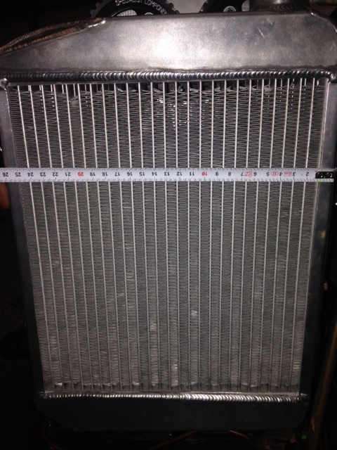
The approach to use an electric cooling fan was taken due to space requirements for the hose work from the head end plate drains to the rear oil return manifold. Measurements were taken and the largest cooling fan was ordered that would fit onto the rear side of the alloy rad. The original front cowling was retained and the mounting positions used to mount up some mounting brackets so that the fan would fit up against the radiator.

The SC ECU and loom has the function to switch negative to a relay to power the fan so wiring should be straight forward.
Pipework and cooling.
Posted: January 17, 2015 in BlockTags: block, bmw, classic mini, engine, engine conversion, k100, lightweight, mini, Mini Twin cam, Rods, stainless manifolds, TWIN CAM., twincam
The conversion gets a little complicated trying to pipe up all of the required lines in so little space. Also having an exposed cam belt running within around 15mm away from a radiator bottom hose can be a little daunting. We now have 2 10mm drain lines, a 25mm drain line from head to block sump. A block breather, a head breather and the modified bottom and top radiator hoses. The hoses that i used for the head drain lines need to be a minimum of 3/8″ or 10mm. The head main drain is 25mm. I used black silicone hoses for the oil and water applications on the engine with nylon hose joiners. A selection of 90, 45 and 180 formed hoses were used to hose up the engine.


As the pictures show the radiator fan is very close running to the head breather pipework at this point the choice was made to run an electric fan mounted to the outside of the radiator to free up some much needed space. Brackets in the pictures above also are for mock up only.
Exhaust manifold wrapping.
Posted: January 17, 2015 in UncategorizedTags: block, bmw, classic mini, engine, engine conversion, exhaust wrapping, k100, mini, stainless manifolds, twincam
With the SC stainless manifolds i decided to wrap them with black exhaust wrapping. I did this to try and remove a little heat from the engine bay and also the bulkhead of the mini. The manifolds pass very close to the subframe cross member and the cars bulkhead panel. The ends are secured by CV boot stainless ties.


In the lower of the two pictures you can also see the M8x1.0 oil supply drilling that i will insert a union to supply the cams.
The manifold studs were renewed using M8 x 40 manifold studs and brass nuts available from all good online auction sites.
Engine out… engine in…..
Posted: January 12, 2015 in UncategorizedTags: block, bmw, cam, classic mini, DTI, engine, engine conversion, gearbox, k100, mini, piston, sale, twincam
Getting the standard original engine out was easy..


Putting this one in was a little more testing but we got there. Its a tight fit around the radiator / fan. Thought will have to take place regarding head oil return pipe lines if using an original cooling fan driven off the water pump.

The original engine is for sale and open to offers as of Jan 2015. Basic spec is a 998 A series bored ‘040 oversize, Stage 3 unleaded head, 266 camshaft, lightened and balanced bottom end and pre-verto flywheel, orange diagram and fully rebuilt gearbox. If you require full list of specs please fill out a contact me form and i will email specs and videos if requested of the engine running in the car prior to removal.
Building up the engine.
Posted: January 12, 2015 in Block, Head, UncategorizedTags: ARP, block, bmw, classic mini, Con rod, engine, engine conversion, gearbox, k100, lightened flywheel, lightweight, mini, Mini Twin cam, piston, stainless manifolds, TWIN CAM.
Once the jackshaft was in and the pulleys fitted the engine was assembled in modular format. The cylinder head was re-assembled and checked again once the camshaft was returned from Piper. The re-profiling worked and the valve gap issue was resolved. This could then be fitted. I used SC’s Silicone / copper head gasket for ease of assembly. Head studs of the 8V K100 engine arrangement have to be shortened in all positions (by approx 7mm in my application). The original BMW head bolt washers are used with new A series flanged head nuts. SC specifies all torque values and tightening sequence in the build manual. Once complete spacing between each camshaft and fasteners have to be checked. A new cast large impeller (without bypass output) water pump was fitted. This needs to be modified along the top edge of the alternator top mount point. This modification is removing material so it allows the cylinder head / SC end cover plate to sit above the water pump body. The original mounting hole is used so care is needed to be taken when modifying to remove enough material to allow the water pump to fit but minimum material to prevent weakening of the alternator mounting. Also a cast rib on the front edge of the water pump needs to be ground back to allow sufficient clearance for the timing belt to run past from crankshaft pulley to inlet cam gear.
Basic cam timing of the engine could then take place. This was completed over the course of an afternoon and checked, double checked and triple checked with various belt / pulley adjustments involved. After adjustments the cam timing was set to SC’s instructions. An accurate DTI is an important and essential tool in this job and also mounting it so it acts in parallel with the inlet valve . The engine was then rotated carefully by hand to see if there was any issues with interferance but everything was fine. Tension of the belt is measured on the length of belt from the exhaust cam to the oil pump (jackshaft) pulley. This is rotation level between thumb and index finger. Its adjusted by the cam tensioner roller as shown at the bottom of the picture. From past projects when this turned up in the SC kit it is from a Ford Pinto engine. This is the cam belt tensioner type if parts are required. The ford part number is: 1 496 915. I will get the details of the belt from the continental model number.

The gearbox was then fitted to the engine body, followed by the MED Roller bearing drop gears, transfer casing and MED clutch and flywheel assembly. Below is the result…


With the SC kit the original camshaft is utilised to run the oil pump from the SC camshaft pulley. The original camshaft can be modified if costs need to be kept down. Or as in my case i decided to purchase a modified camshaft / jackshaft from SC. The redundant cam lobes have been removed reducing the rotating mass inside the engine case. These modifications allow a constant flow of oil up through the original block rocker arm supply casting. As the head oil feed was welded with its original modifications you can re-drill the head to link the block to the head gallery. By doing this the cams will be lubricated through an internal gallery circuit.


I decided that i did not wish to re-drill and intersect the heads original oil feed gallery so i ran an external oil feed hose from the oil pressure switch union on the front of the block via a T piece to the plugged port on the rear side of the BMW head. This thread is M8x1.0 thread and unions are available to fit this port direct just remove the factory allen bung and job done.

The oil pump that was fitted was a A+ spade drive turbo oil pump. This was supplied by minispeed.
